Calvin & Hobbes

Modular Preamplifier with battery power supply.
My ´professional´career started with the ´Calvin & Hobbes´ as part of my thesis.
Calvin, the preamplifier itself, is a modular concept, featuring 6 input channels, 2 independent tape-loops, as well as highlevel-outputs and one headphone output.
Hobbes is a battery power supply, which powers Calvin. Rechargeable lead-acid batteries are used as power source.

Calvin makes extensive use of OP-amps throughout.
The highevel inputs run into Pots to trim to similar volume levels to avoid large volume steps when switching channels and to supply for constant imput impedance values of 47kOhms. Simple gain-stages with a gain of 2 (+6dB) follow, which also guarantee a very low output impedance. This keeps interchannel crosstalk low even with long PCB-traces and reduces emf-sensitivity of the traces.
The Tape-loops feature buffer stages with low output impedance and a gain of 0.5 (-6dB), so that Input- and output-levels are equal.
Input channel 1 is the only one without a input buffer stage. Its intended for useage with sources that have a high enough signal voltage level and already low enough output impedance, e.g. a external Phono-stage.
The input switching matrix follows, using relais. Here the audio signal splits in two paths. The first runs into the volumecontrol-, then the Balance-Pot (each 10kOhm-types) and finally a gain-of-3 amplifying stage. This gain stage is also capable to produce a balanced output signal and works with a discrete transistor booster stage.
The second parallel path is on-switchable on demand. It runs into a volumecontrol-Pot and a headphone amplifier featuring a discrete transistor booster, with a gain of 7.
Highlevel buffer- and amplifier stages
The term operational amplifier describes a certain amplifier topolgy, that typically features two input pins, a output pin and two power supply pins.
Other than that the OP is regarded as a ´black box´. The parameters specified in the Datasheet characterize the behaviour of the ´black box´.
Over time one began to understand OP-amp as an integrated circuit in general, so that other integrated circuits like instrumentational amplifiers (INA) are now also regarded as
OPs.
Characteristic parameters of an ideal OP-amp are:
- infinitely high openloop-gain (OL-gain)
- infinitetly high input impedance
- infinitely large bandwidth
- infinitely small output impedance
In praxis the real OP-amp misses these goals by far.
Especially the OL-gain and the OL-bandwidth are grossly limited and frequency dependent.
Without the corrective and linearising function of the feedback-loop the OP-amp is a integrating, not an amplifying device.
The concept of feedback works -within certain limits- so well that very good behaviour can be measured.
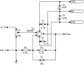
This is the schematics of the buffer stage:
The Pot P1 defines the input resistance and allows to trim the input volume level.
The audio signal runs into the non-inverting pin of the OP-amp K1 and is amplified with a gain of 2 (+6dB). The formula to calculate the gain is: A=1+R2/R1.
The bandwidth is limited with the small capacitor C1 in parallel to R2.
The capacitors C2-C5 help to clean up and to stabilize the power supply voltages.

The schematics of the actual amplifier stage is more complex.
For one are the OP-amp outputs boosted by discrete transistors, and for second, a almost identical but inverting amplifier stage is implemented by U2, which allows to drive balanced audio signal after professional standards.
The gain of the noninverting branch around U1 calculates after the formula A=1+R3/R2=7 (+9.5dB/0°). For the inverting branch the formula reads A=R12/R11=7 (+9.5dB/180°).
The signal current through R8, resp. R17 into the load, is also routed via the trimmable capacitors C1, resp. C4 to the inputs of the OP-amps.
Capacitive loads like different cables and cable lengths, could in the extreme lead to oscillations. This is easily detectable with an oscilloscope and feeding a rectangular signal of 10kHz frequency. One can trim and optimize the behaviour to the rectangular signal by varying the value of capacitors C1, C4. This technique reduces the bandwidth of the amplifier, but a bandwidth limit between 300-500kHz is more than sufficient in this case.
The possibilty to tune-in on a optimal, load-independent behaviour of the amplifier renders any discussion about cable-sound obsolete.