Calvin-phono/PlatINA/RP1
The Calvin-phono, the PlatINA and the RP1 are very flexible, universally useable phono-preamplifiers. The PlatINA is a project discussed in a same-titled thread in the forum of the AnalogueAudioAssociation (AAA) in which I assisted with suggestions and ideas from the experiences made in the construction process of the Calvin-phono.
http://www.analog-forum.de/wbboard/index.php?page=Thread&threadID=34957&pageNo=1&highlight=INA103 AAA-forum Thread
http://www.crazy-audio.com/projects/platina PlatINA Website
The RP1 is the incarnation of a befriended user, designed mostly after my proposals.
The associated thread can be found at the HiFi-Forum here:
http://www.hifi-forum.de/index.php?action=browseT&forum_id=103&thread=87
HiFi-Forum, RP1 by user ´Köter´ (Doggy)
There are also threads at the DIY-Audio forum, dealing with very similar phono stages that utilize the INA103 or INA163.
For the design of the PlatINA and the RP1 important circuit design and PCB-layout suggestions were provided by me, based on the design and experiences with the Calvin-phono, the phono-stage of my Calvin&Hobbes preamplifier.
What makes these Phono-Preamps so special is the combination of great flexibility, superb measurements and excellent sound.
Features:
- can accomodate nearly any pickup system, from low-output MCs to high-output MMs
- switchable resistances and capacitances for optimal pickup loading
- gain switchable over a great range
- either unbalanced or balanced input mode
- highly precise equalizing curve after RIAA-IEC 1963 (20Hz subsonic filter) switchable
- HF-equalizing after RIAA-Neumann switchable
- balanced or unbalanced outputs (working in parallel)
The circuit design of the Phono-Preamps is a result of the consequent implementation of the specifications. Differences between the three devices are due to the choice and dimensioning of parts and the balanced output of the PlatINA and the RP1, as well as a different PCB-layout and power supply.
All common pickup systems are true balanced signal sources. But most MM-pickups are manufactured unbalanced with a small metal strip going from one signal pin to GND.
To accommodate for both the phono-input stage should be switchable between balanced and unbalanced mode.
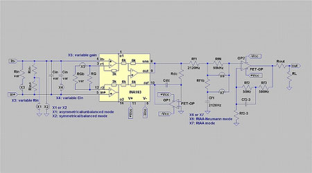
Correction: The function of the jumpers X1 and X2 in the principle schematics must be interchanged. X1 jumpers the balanced mode, X2 the unbalanced mode.
The best input stage for a balanced signal source comes in form of a instrumentation amplifier, or short INA. A INA offers at its both inputs
exactly equal conditions, which a simple OPAmp doesn´t.
To load the pickup optimally a row of resistances (Rinvar) and capacitances (Cinvar) can be switched. Additionally GND may be switch-connected to the inverting input pins for the unbalanced input mode.
INAs come with unbalanced or with balanced outputs. The latter are called fully-differential INAs. A fully-differential signal routing within a device presents no real advantage though, since the GND-related circumstances can be defined quite well, and can be controlled easily by the layout-design.
A fully-differential signal path relates rather more to double the effort, and increased parts number count and cost.
The Phono-Preamps here make use of a INA with unbalanced output. The INA103 and INA163 of TI/BB come into consideration (similar INAs are available from ADI and THAT Corp.). Both feature a Ref-Pin usually connected to GND.
A active DC-servo stage, comprised of a FET-input OP-amp (OP1) steers the output Offset via the Ref-input to 0Vdc. The required high gains of the INA-stage and the need for high overload reserves almost dictate the application of a DC-servo at this point.
The RIAA-IEC equalizing curve specifies a lower cut-off frequency of 20Hz to reduce the danger of Tonearm-pickup resonance-feedthrough.
Instead of designing the DC-servo to the usually chosen 0.1Hz cutoff frequency it is advantageous and easy to design it to the 20Hz cutoff frequency (Rdc/Cdc).
Tough it would be possible and theoretically wishful to connect the RIAA-equalizing network into the feedback loop of the INA, I designed it as a linear gain amplifier. Its gain is variable over a great scale with the single resistor RG. The RIAA-equalization curve asks for tightest tolerances of the frequency decisive parts, if the CMRR (CommonModeRejectionRatio, the immunity against external induced noise) should remain high.
If the requirements regarding noise performance and overload headroom can be fulfilled, this kind of input stage is very favourable with regard to flexibility, circuit effort and performance.
The noise performance of the INAs is in fact so good that regardless of the inherent -3dB noise penalty of balanced inputs, even very-low output MC-pickups, providing for just 150µV of signal voltage (norm-level@1kHz, @5cm/sec cutting velocity) can be accommodated.
Following the linear INA-input gain stage comes a passive 2120Hz-filter (Rf1+Rf1b/Cf1) that´s series resistance part was chosen so low-ohmic in value that the signal loss of the filter remains below 10%.
A jumper at this point decides over equalizing after RIAA (X7) oder RIAA-Neumann (X6). The Neumann-curve accounts for the real world behaviour of the cutter head of the cutting lathe machine. It results in a higher upper bandwidth limit in the amplitude response curves. The effort of implementing this option reduces to the addition of just one jumper and one resistor.
The missing 50Hz-500Hz equalizer can be found in the following stage. The frequency decisive parts Rf2, Rf3, Cf2-3 and Rf2-3 are located in the feedback loop of the FET-OPamp OP2.
Compared to a fully passive equalizer this split-in-2 concept offers the advantage of 20dB less required gain and superior noise- and distortion-figures.
Against single-stage fully-active equalizing it offers the advantage and the freedom to optimize parts values for improved signal handling and noise performance and the easy implementation of the Neumann-RIAA. The very high gain-factors required by low-output MC pickups can´t be generated in high quality in a single stage design anyway.
Indeed is the gain of the OPamp OP2 @1kHz low and doesn´t add much to the overall gain of the phono-stage. The INA does all the hard work.
The OPamp functions as low ouput impedance source at the same and doesn´t need the assistance of a dedicated buffer or driver stage.
If wanted a dedicated Balanced Line Driver like the SSM2142 from ADI or a DRV134 from TI/BB can supply for balanced outputs signals as its been done with the PlatINA and optionally also with the RP1.
With relatively low parts- and cost-effort this circuit topology of split equalization and two gain stages allows for a very high-quality phono playback performance, combined with high flexibility regarding the choice of pickup systems.
With a tolerance range of 1% of the frequency decisive parts less than +-0.1dB amplitude deviation can be achieved over the full audio frequency range.
Noise and Distortions stay well within irrelevant orders of magnitude.
Sonically all three Phono-Preamps perform very neutral. Bass is reproduced very detailed and contoured. Based on this solid fundament the mids and highs perform with a very high level of resolution.
Even pickup battleships like a Koetsu Urushi or a Lyra Titan-i are not too much for the phono, but can really shine and show all their qualities.
As I find the RP1 especially well executed electrically and mechanically, I´d like to show some pics:


One can see the division in to two distinct chambers inside of the casing -which is a modification of a Modushop casing- that accommodate the power supply and the audio-PCB subassemblies. The routing of the cabling is very well executed, enhacing the devices perfect looks.
The PCBs are single layer and could even be etched at home.
The Layout uses plenty of PCB-space making mounting and soldering of the parts quite easy.
Parts are mostly of throughhole style. Only the INA163 and a couple of ceramic blocking caps are SMD style and are mounted on the copper side of the PCB.
On the third and fith pic You can see a Jumper between the two DIP-8 OPAmp sockets. Here You can insert a volume control, if You want to provide the RP1 with a variable output level.